Knowledge Base
Antenna Measurements
Testing of real antennas is fundamental to antenna theory. All the antenna theory in the world doesn't add up to a hill of beans if the antennas under test don't perform as desired. Antenna Measurements is a science unto itself; as a very good antenna measurer once said to me "good antenna measurements don't just happen"
What exactly are we looking for when we test or measure antennas?
Basically, we want to measure any of the fundamental parameters listed on the Antenna Basics page. The most common and desired measurements are an antenna's radiation pattern including antenna gain and efficiency, the impedance or VSWR, the bandwidth, and the polarization.
The procedures and equipment used in antenna measurements are described in the following sections:
Required Equipment and Ranges
In this first section on Antenna Measurements, we look at the required equipment and types of "antenna ranges" used in modern antenna measurement systems.
Radiation Pattern and Gain Measurements
The second antenna measurements section discusses how to perform the most fundamental antenna measurement - determining an antenna's radiation pattern and extracting the antenna gain.
Phase Measurements
The third antenna measurements section focuses on determining phase information from an antenna's radiation pattern. The phase is more important in terms of 'relative phase' (phase relative to other positions on the radiation pattern), not 'absolute phase'.
Polarization Measurements
The fourth antenna measurements section discusses techniques for determining the polarization of the antenna under test. These techniques are used to classify an antenna as linearly, circularly or elliptically polarized.
Impedance Measurements
The fifth antenna measurement section illustrates how to determine an antenna's impedance as a function of frequency. Here the focus is on the use of a Vector Network Analyzer (VNA).
Scale Model Measurements
The sixth antenna measurement section explains the useful concept of scale model measurements. This page illustrates how to obtain measurements when the physical size of the desired test is too large (or possibly, too small).
SAR (Specific Absorption Rate) Measurements
The final antenna measurement section illustrates the new field of SAR measurements and explains what SAR is. These measurements are critical in consumer electronics as antenna design consistently needs altered (or even degraded) in order to meet FCC SAR requirements.
Required Equipment in Antenna Measurements
For antenna testing, the most fundamental device is the VNA [Vector Network Analyzer]. The simplest type of VNA is a 1-port VNA, which is able to measure the impedance of an antenna [which is equivalent to measuring S11 and VSWR]. More of this will be discussed in the impedance section
Measuring of an antenna's radiation pattern, gain and efficiency is more difficult and requires a lot more equipment. We will call the antenna to be measured the AUT, which stands for Antenna Under Test. The required equipment for antenna measurements include
A reference antenna - An antenna with known characteristics (gain, pattern, etc)
An RF Power Transmitter - A way of injecting energy into the AUT [Antenna Under Test]
A receiver system - This determines how much power is received by the reference antenna
A positioning system - This system is used to rotate the test antenna relative to the source antenna, to measure the radiation pattern as a function of angle.
A block diagram of the above equipment is shown in Figure 1

These components will be briefly discussed. The Reference Antenna should of course radiate well at the desired test frequency. Reference antennas are often dual-polarized horn antennas, so that horizontal and vertical polarization can be measured at the same time
The Transmitting System should be capable of outputing a stable known power level. The output frequency should also be tunable (selectable), and reasonably stable (stable means that the frequency you get from the transmitter is close to the frequency you want, does not vary much with temperature). The transmitter should contain very little energy at all other frequencies (there will always be some energy outside of the desired frequency, but there shouldn't be a lot of energy at harmonics, for instance).
The Receiving System simply needs to determine how much power is received from the test antenna. This can be done via a simple power meter, which is a device for measuring RF (radio frequency) power and can be connected directly to the antenna terminals via a transmission line (such as a coaxial cable with N-type or SMA connectors). Typically the receiver is a 50 Ohm system, but can be a different impedance if specified
Note that the transmit/receive system is often replaced by a VNA. An S21 measurement transmits a frequency out of port 1 and is records the received power at port 2. Hence, a VNA is well-suited to this task; however it is not the only method of performing this task
The Positioning System controls the orientation of the test antenna. Since we want to measure the radiation pattern of the test antenna as a function of angle (typically in spherical coordinates), we need to rotate the test antenna so that the source antenna illuminates the test antenna from every possible angle. The positioning system is used for this purpose. In Figure 1, we show the AUT being rotated. Note that there are many ways to perform this rotation; sometimes the reference antenna is rotated, and sometimes both the reference and AUT antennas are rotated.
Now that we have all of the required equipment, we can discuss where to do the measurements.
Where is a good place for our antenna measurements? Maybe you would like to do this in your garage, but the reflections from the walls, ceilings and floor would make your measurements inaccurate. The ideal location to perform antenna measurements is somewhere in outer space, where no reflections can occur. However, because space travel is currently prohibitively expensive, we will focus on measurement places that are on the surface of the Earth. An Anechoic Chamber can be used to isolate the antenna test setup while absorbing reflected energy with RF absorbing foam.
Free Space Ranges (Anechoic Chambers)
Free space ranges are antenna measurement locations designed to simulate measurements that would be performed in space. That is, all reflected waves from nearby objects and the ground (which are undesirable) are suppressed as much as possible. The most popular free space ranges are anechoic chambers, elevated ranges, and the compact range.
Anechoic Chambers
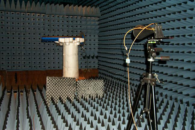
Anechoic chambers are indoor antenna ranges. The walls, ceilings and floor are lined with special electromagnetic wave absorbering material. Indoor ranges are desirable because the test conditions can be much more tightly controlled than that of outdoor ranges. The material is often jagged in shape as well, making these chambers quite interesting to see. The jagged triangle shapes are designed so that what is reflected from them tends to spread in random directions, and what is added together from all the random reflections tends to add incoherently and is thus suppressed further. A picture of an anechoic chamber is shown in the following picture, along with some test equipment:

The drawback to anechoic chambers is that they often need to be quite large. Often antennas need to be several wavelengths away from each other at a minimum to simulate far-field conditions. Hence, for lower frequencies with large wavelengths we need very large chambers, but cost and practical constraints often limit their size. Some defense contracting companies that measure the Radar Cross Section of large airplanes or other objects are known to have anechoic chambers the size of basketball courts, although this is not ordinary. Universities with anechoic chambers typically have chambers that are 3-5 meters in length, width and height. Because of the size constraint, and because RF absorbing material typically works best at UHF and higher, anechoic chambers are most often used for frequencies above 300 MHz
Elevated Ranges
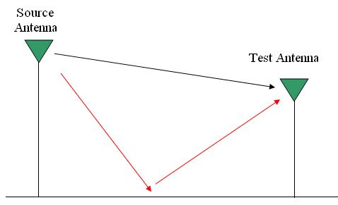
Elevated Ranges are outdoor ranges. In this setup, the source and antenna under test are mounted above the ground. These antennas can be on mountains, towers, buildings, or wherever one finds that is suitable. This is often done for very large antennas or at low frequencies (VHF and below, <100 MHz) where indoor measurements would be intractable. The basic diagram of an elevated range is shown in Figure 2

The source antenna (or reference antenna) is not necessarily at a higher elevation than the test antenna, I just showed it that way here. The line of sight (LOS) between the two antennas (illustrated by the black ray in Figure 2) must be unobstructed. All other reflections (such as the red ray reflected from the ground) are undesirable. For elevated ranges, once a source and test antenna location are determined, the test operators then determine where the significant reflections will occur, and attempt to minimize the reflections from these surfaces. Often rf absorbing material is used for this purpose, or other material that deflects the rays away from the test antenna.
Compact Ranges
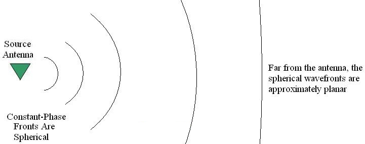
The source antenna must be placed in the far field of the test antenna. The reason is that the wave received by the test antenna should be a plane wave for maximum accuracy. Since antennas radiate spherical waves, the antenna needs to be sufficiently far such that the wave radiated from the source antenna is approximately a plane wave - see Figure 3.

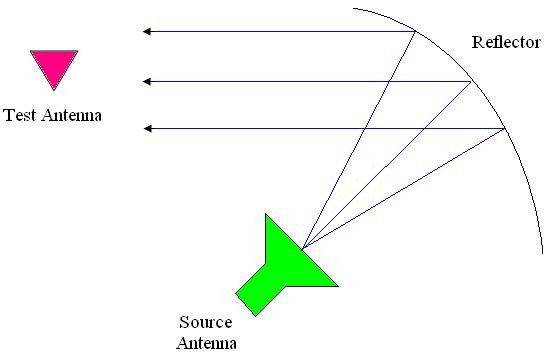
However, for indoor chambers there is often not enough separation to achieve this. One method to fix this problem is via a compact range. In this method, a source antenna is oriented towards a reflector, whose shape is designed to reflect the spherical wave in an approximately planar manner. This is very similar to the principle upon which a dish antenna operates. The basic operation is shown in Figure 4.

The length of the parabolic reflector is typically desired to be several times as large as the test antenna. The source antenna in Figure 4 is offset from the reflector so that it is not in the way of the reflected rays. Care must also be exercised in order to keep any direct radiation (mutual coupling) from the source antenna to the test antenna.
Previous:Antenna Fundamentals
Next:WIFI Antenna Design